Andreas just received his new RC Timer Gimbal and Martinez controller. I went over to assist with the build and take some pictures. Here's the parts as they came from RC Timer. Note that you need to order the motors in addition to the gimbal and controller. The motors are included as part of the gimbal kit. There's an RCG thread.
Here's everything out of the package. There was one bolt missing. Be careful with the bag that contains the grub screws and C rings. They're really tiny.
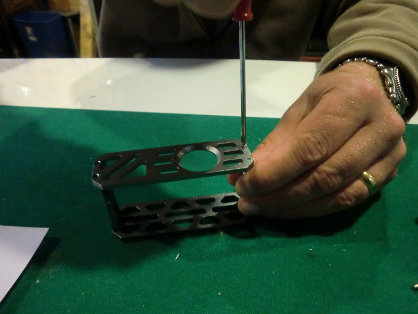
Step 1: assemble the main camera mount.
It's pretty simple, just bolt the pieces together.
Be sure that the grub screw holes both face forward. A GoPro should friction-fit in the frame pretty securely.
Next, assemble the outside frame.
Oops, a problem! The side mount bolt hole was not properly beveled, so the bolt does not fit through the hole with enough length to attach to the edge piece.
We drilled a bevel using a larger drill bit. That fixed the problem nicely.
Here's the outside frame assembled.
Next, assemble the bearings. Careful with the little pieces!
We found a problem with the grub screw hole. It wasn't properly tapped, so we couldn't get the grub screw inserted all the way. After some debugging, we ended up switching the two sides, so the working grub screw was on the motor side.
The grub screw uses a 1.25mm hex wrench. It would be nice if RC Timer included one. They don't, so be sure and have one ready.
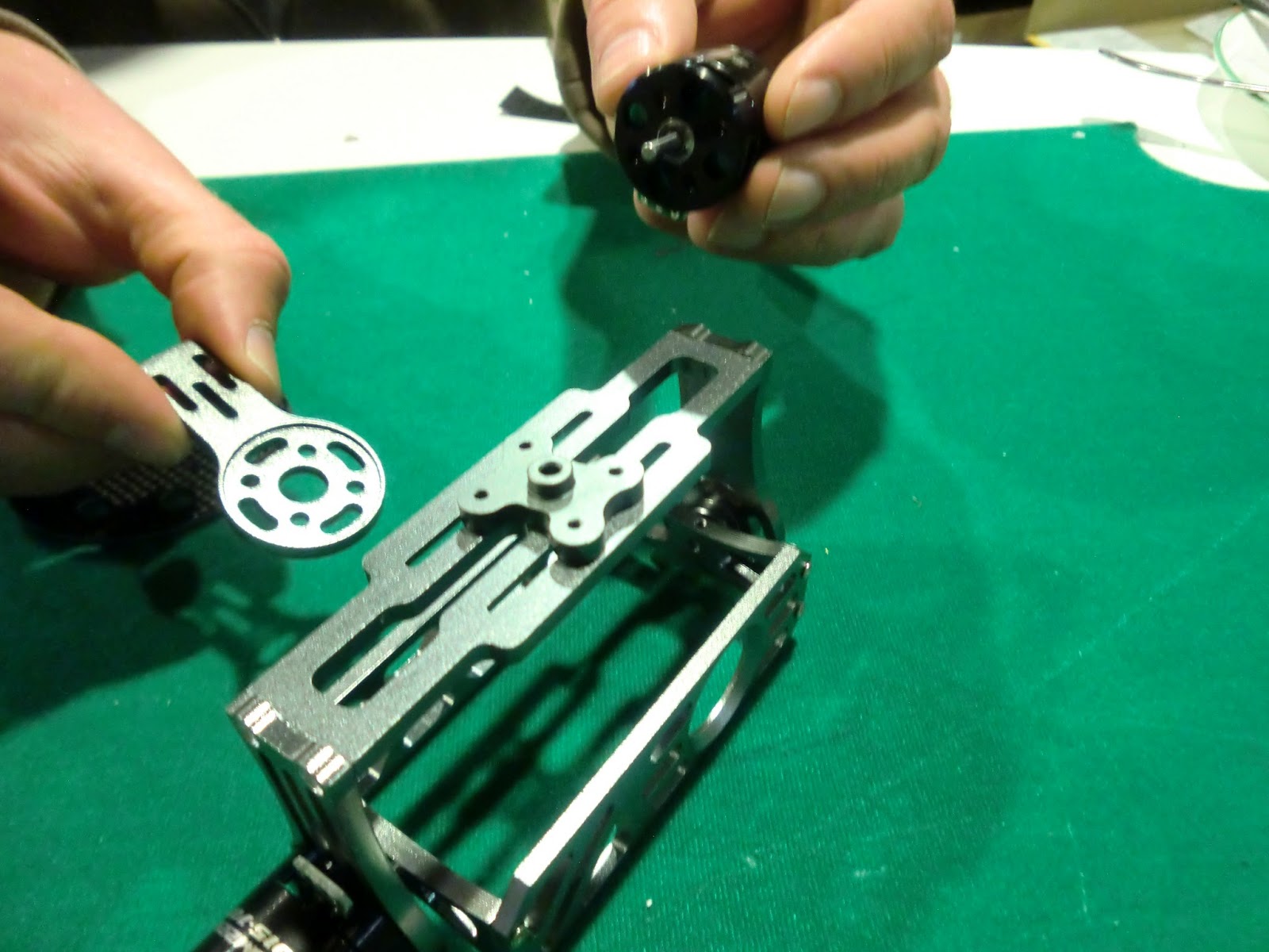
Here's how the yaw motor fits onto the gimbal.
It attaches just like the pitch motor.
Be careful attaching the C rings. If you have some snap ring pliers use them.
Here's the outside frame attached to the inside frame. Both sides have a shaft, grub screw, and C ring.
Here's how to attach the yaw motor.
Make sure you have the indentations properly aligned. Dry fit it together to make sure.
One of the tapped holes was a bit malformed, and the 3mm bolt didn't fit through. You can clean it out with a 3mm drill bit, or tap a 3mm bolt through the hole with a hammer a couple of times. As good as new!
Here's the pieces of the yaw arm, getting ready to attach.
Another grub screw. Make sure it goes all the way through the hole.
Ready to attach the yaw arm.
Attaching the yaw arm to the frame mount.
Attach the 3mm nylon risers to the frame mount.
And then attach the board to the risers.
And attaches to the bottom plate of the anti-vibration unit.
Stick the rubber anti-vibration pieces (anybody know what these are called? Leave me a comment!) onto the top and bottom plates. Do this after attaching the bottom plate to the gimbal.
Soldering is pretty simple. Snip the wires and re-tin them with a generous portion of solder. Tin the motor pads. Put each wire on the corresponding solder pad, and touch the wire with the soldering iron, attaching the wire. If it takes more than a second you're doing it wrong. Note that since this is a three-phase motor, the order of the wires doesn't matter.
Here's what it looks like when it's finished. Later you can cover the soldered connections with hot glue for physical strength and to insulate the wires.
The left and right connectors are for the yaw and pitch motors respectively. (TODO: double check this!)
Note that we were doing the power wrong! Don't use a 5V servo connection, use a 2S-4S battery. Be sure and watch the polarity. It may not be a bad idea to put a battery connector onto the board.
Andreas for some reason had this nifty little sawhorse sitting around from another project, and it made a perfect test mount.
Here's the completed unit, ready to test.
We used a grinding stone to flatten out one side of the motor shaft. We did this while we were trying to debug the grub screw problem mentioned above. You may not have to do this.
Just for fun, I made a time lapse of the construction.
To be continued... configuration, software, and tuning