Showing posts with label _toc:3DR Radio. Show all posts

Telemetry Cable for the 3DRobotics Radio

Here's how to make a telemetry cable for the 3DR Radio.  It's slightly different than the one 3DR sells. The 3DR cable has a 5-pin connector on the radio side.  I like the 6-pin connector with an empty pin because it reduces the number of ways the connector can be incorrectly hooked up to the radio.

If you do much of this kind of stuff, you owe it to yourself to get the most excellent crimping set from Hansen Hobbies.  Here's some notes on cable making in case you're interested:

http://www.hansenhobbies.com/products/connectors/connectorkits/ck_drcck1/
http://hobbyrcs.blogspot.com/2012/05/miles-of-free-servo-wire.html
http://hobbyrcs.blogspot.com/2011/02/crimping-connectors.html

(TODO picture of radio end)
(TODOpicture of APM end)


Cable (4 wires)

Radio          APM       Color
-----          ---       -----
1. GND (BLK)   1. GND    Black
2. CTS            empty
3. 5V          2. 5V     Red
4. RX          3. Tx     White
5. TX          4. Rx     White
6. RTS            empty


Strain Relief Carrier for 3DR Ground Module

Thanks to a comment by Andreas M. Antonopoulos about the fragility of the USB connector, I made a small ground module case that seems to provide a lot of strain relief.
 It's pretty simple -- I cut it out of thin cardboard, scoring the cardboard so it would fold neatly around the unit and the USB connector.  The scorings are 10mm, 20mm, 10mm apart.  I cut out a window to see the LEDs on the board.
 Here it is all taped up.  The tightest part is wrapped around the USB connector.  Tomorrow I'll leave it plugged in for a while and make sure it's not getting too hot.  If it is, I'll try expanding the hole, or even just trimming it off and only keeping the strain relief on the USB part of the board. (update: no apparent heat buildup at all.)
 I taped the side with strapping tape to keep the rectangular shape and put a piece of velcro on it.  If I had a 3D printer or a laser cutter I would probably go crazy making stuff like this, but the cardboard seems to work nicely.
 I didn't want the cable catching on things, so I ordered a 1 foot USB extension cable from Amazon and used that cable instead of the one that shipped with the unit.  I pulled the cable around the back just enough so that it removed the slack, but not so much that it caused any strain for the USB port.  A right-angle USB cable would be perfect, but I don't think I've seen one.
Here's the view from the back.  I'll measure the signal strength later and make sure I'm not causing any interference.

Setting the Network Address on the 3DR air radio

 As I was mentioning in the previous post, everything went smoothly and I'm currently in love with my new 3DR radio.  Thanks Tridge, once again I'm in your debt!

The only snag I hit was when I was changing the network ID away from the default.


 I followed the directions to do so, and everything went great up until I saved the settings.  I got a popup indicating that the air unit had an error saving the settings.  Like Han Solo, I had a bad feeling... I might now have the two units set to two different network ids: the ground radio updated to 26, and the air radio still on 25.


That's indeed what seemed to be the case:  reloading the settings worked fine for the ground radio, but the air radio couldn't be contacted.

At this stage I could have tried resetting the ground radio back to network 25.  That would have been the easiest thing to try, and would have worked fine to get the radios talking.


But I had noticed that the air radio pins were a standard FTDI connection, so I had another thought.  Perhaps I could connect the air radio to the computer via an FTDI adapter, and set it to network 26 that way.  I have the industry standard sparkfun FTDI adapter, so I gave it a try.


And hooray, it worked.  Hook it up, start up the APM software, select the proper COM device and set the baud rate to 57600. DO NOT try and connect. Select Configuration/3DR Radio to bring up the configuration screen. "Load Settings" worked as expected, and showed that I was correct in thinking that the network ID was still 25.  I changed to to 26, saved, put the air unit back on the APM, and reattached the ground unit.

I ran the APM Planner again, and everything worked like a charm.  I could read (and set!) the air radio settings, and connecting the APM in the APM planner worked as expected.


(toc: 3DR Radio)

Review: 3DR 900MHz Radio

 The much-anticipated 3DR radio arrived yesterday, in the stylish new 3DR black box.  Hooray!  After having so much xbee grief, I had high hopes that this would solve all my telemetry-related problems.

TLDR: it's great!

As advertised, the kit comes with a ground radio, an air radio, two antennas, cables for each, and a header for the air radio.  As a nice bonus, they included enough 1-1/4'' shrink tube to cover both radios. Nice!
 Here's what the radio units look like. The ground unit plugs directly into a USB.  Both Mac and Windows 7 recognized it and downloaded the proper driver.  The included ground cable is a standard USB extension cable. (Use the cable, and don't plug the ground unit directly into a USB port.  There's no other attachment to the board other than the soldered connections, so the USB connector will break off if there's any stress applied while in the computer's USB port.  Thanks to Andreas Antonopoulos for this tip!)
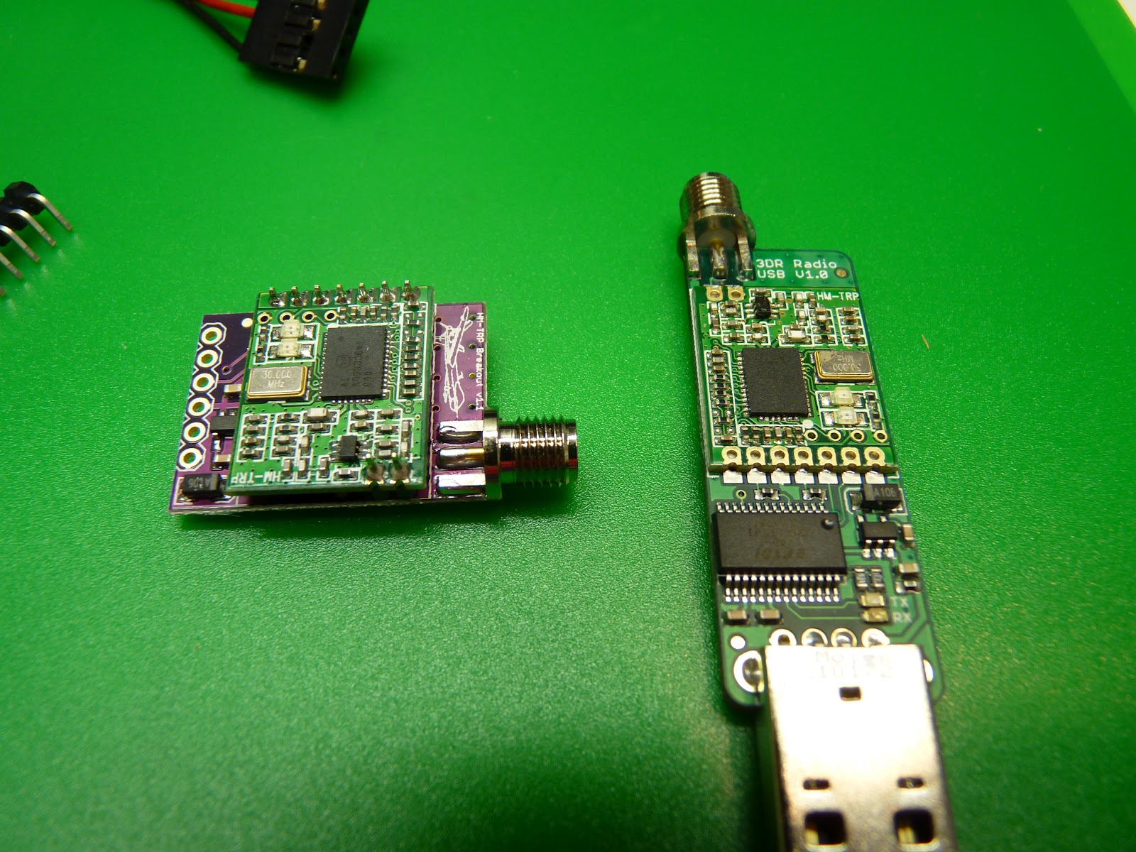
 As you can see here, the air unit doesn't have the headers soldered on.
 The approximate weight of the air unit is 17.4 grams, not counting solder or shrink tube.  It's possible to replace the antenna with a lighter quarter-wave wire antenna.  Tridge mentioned that he did some of his initial testing with such a setup.
 Stick a label onto your antenna before you get it mixed up with a 2.4GHz or other sized antenna.  They look pretty similar but won't work.


 Here's how to attach the air unit cable.  Use the end of the cable that has the 5-pin plug.The RTS pin is left bare, and the wire gap is closest to GND.  If you've got the red wire on 5V you're good -- there's only one orientation where that works.
Here's the air unit shrink wrapped and with cable attached.
 Here's the radio pins on the APM2.  It's located at the rear of the board.  There are four pins, and you use the end of the cable that has the four-pin connector.
 Looking forward (as in this picture), the red power wire is towards the left.


 Once the air unit is hooked up, power on the APM, attach the ground unit to your computer (via USB), run the APM planner, and press control-A.  Be sure to be in disconnected mode.  You will get the 3DR radio configuration screen. Press "Load Settings" and you should get the settings for both the ground and air radios.  Exit this screen, and you should be able to connect as normal.  The configuration was read immediately (no "timeout in ..." messages!!) It took about 5 seconds from connect time for the APM Planner to start responding.

Once you've verified it's working, you will want to change the network ID if you're planning on flying near anybody else using a 3DR radio.

Summary:  overall I'm very happy.  I spend about an hour setting things up (including taking pics and notes), and it's working smoothly.

Viewing Radio Stats

Michael Oborne points out: 'in the planner under "Status" and "tuning" you can see all the values tridge included in his graph live.'


What to do if your network binding goes awry

Of course, this would not be a certified Mark Harrison Radio Experience (tm) if at least one thing did not go wrong.  In this case, changing the network ID failed on the air radio, so I was stuck with a ground radio with an ID of 26 and an air ID of 25.  Fortunately this was not too difficult to clear up; I'll cover that in the next post. (update: here.)


Older Post ►
eXTReMe Tracker
 

Copyright 2011 Hobby-RC s is proudly powered by blogger.com